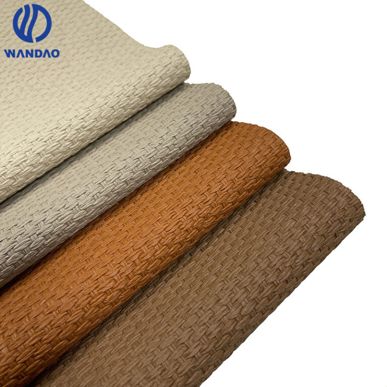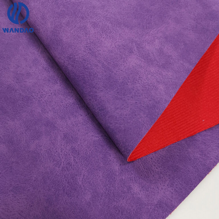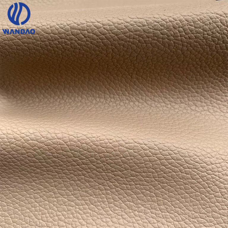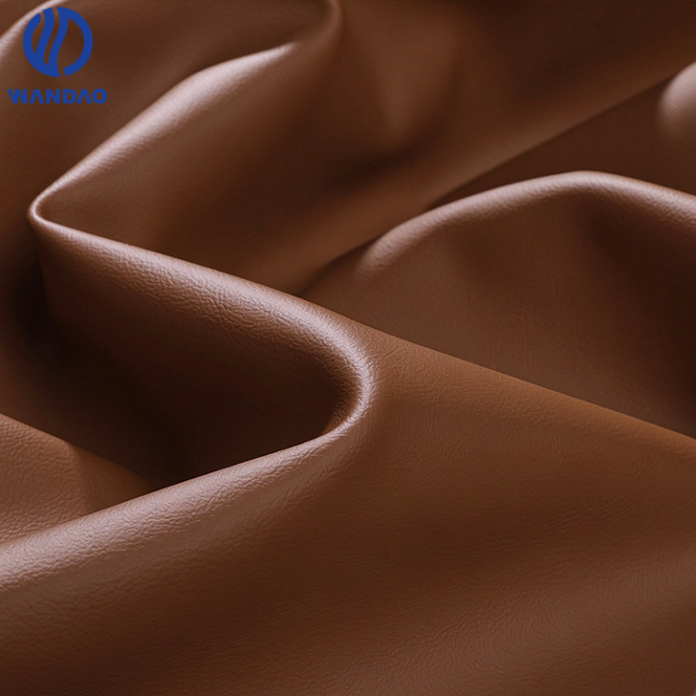
Automotive trim grain distortion should be assessed on the formed door insert as well as the incoming flat material. Map the affected regions, compare them with the approved flat and formed references, and connect each observation to the documented construction and forming process. Stretched-looking texture, flattening, whitening and colour mismatch are separate findings. A material tensile result or a free-heat shrinkage report cannot by itself approve the appearance of a constrained three-dimensional trim component.
Confirm the forming route and the visible surface
Identify the actual process before discussing a defect. A wrapped insert, a vacuum-formed skin and another bonded construction should not be treated as one generic operation. Record the material layers, substrate, adhesive where used, tool identity and approved process revision.
For a PU automotive trim candidate, ask whether the proposed construction has been offered for the intended conversion route. Do not assume that every coated upholstery material can be formed by the same process or equipment settings.
Name the visible finish and orientation on the drawing. Retain a flat material master and an accepted formed-part reference where available. They answer different questions: what was supplied and what the complete converted component is required to look like.
Map automotive trim grain distortion by zone
Divide the insert into useful inspection regions such as a broad field, shoulder, radius, corner and perimeter return. Use the actual part geometry rather than a generic photograph. A local issue at a draw region should not disappear inside an overall statement that the colour looks acceptable.
Record what changed at each region. Separate apparent grain enlargement, loss of definition, directional change, whitening, gloss variation and visible damage. These are observations to investigate. Avoid calling every light patch pigment variation or every flattened area excessive heat without a controlled comparison.
| Observation | Comparison to make | What not to infer alone |
|---|---|---|
| Elongated-looking grain | Mapped location against flat and formed references | A universal allowable stretch ratio |
| Reduced grain definition | Like-shaped parts under matched lighting | One confirmed process cause |
| Local whitening | Before-and-after surface condition | A batch colour error without investigation |
| Broad shade difference | Incoming material and accepted master | That forming necessarily caused it |
| Edge or corner damage | Construction and local process record | Acceptance of the entire part from a sound centre |
Keep colour evaluation and grain approval distinct
SAE J361, October 2022, addresses visual colour matching of automotive parts and materials, including interior soft trim. Its scope does not supply a universal limit for grain distortion in a formed PU door insert. Use the customer’s appearance specification for that separate requirement.
Define the inspection light, view, part orientation and reference. A curved shoulder and a flat swatch present the surface differently. Compare equivalent geometry when judging the finished component, while retaining the flat sample for incoming-material identity and appearance checks.
If numerical colour or gloss measurements are required, have the laboratory define suitable locations and presentation. Keep those readings with the visual observations. A favourable average should not override a local defect when the drawing or appearance agreement evaluates that region separately.
Image placeholder: Door-insert zone map with broad field, shoulder, radius and return identified beside flat and formed appearance references. No invented allowable strain or approval badge.
Record the baseline before conversion
Inspect and photograph the incoming material under the agreed arrangement. Identify grain direction, material code, finish and batch. Retain an unprocessed reference from the trial source. This allows the team to ask whether a feature existed before forming instead of assigning every observation to conversion.
Record specimen location within the trial layout where useful. If several pieces are cut in different directions, label them. A comparison that loses orientation can make it difficult to distinguish a material difference from a layout choice.
Check the completed layer stack before the forming trial. If the production design includes foam, backing or adhesive, identify them and their relevant preparation. A demonstration with a different stack should be labelled as development screening rather than a production-intent part.
Use diagnostic mapping without creating a false material limit
For development, the engineering team may use a suitable reference grid or other tracking method to understand local deformation. Confirm that the marking method does not alter the surface or process being investigated. Keep diagnostic specimens distinct from appearance masters.
Record the pre-process and post-process observations through a repeatable measurement procedure. On a curved part, define how positions and distances are compared. A photograph taken from a different perspective should not be treated as a direct strain measurement without appropriate correction.
Use the map to identify where a further comparison is needed. Do not derive a universal forming limit from one successful part or from elongation at break on a flat strip. The accepted surface appearance may be a different endpoint from material rupture.
Keep process changes controlled
Retain the approved process record for each trial, including relevant material preparation, tooling and forming conditions. Qualified process personnel should select and control those settings. This guide does not provide a generic temperature, pressure, vacuum or dwell recipe.
Where practical, compare one planned change against the baseline. For example, investigate a nominated material revision on the same approved tool and process before changing several other inputs. If the development requires a new combined route, describe the result as approval of that combination.
Record deviations and interruptions. A part reworked by an undocumented extra heating step should not be compared as though it followed the normal route. Rework may need its own validation and should not obscure an unresolved normal-production concern.
Distinguish forming from free-heat dimensional change
A free material specimen exposed to heat answers a different question from a sheet held, drawn or bonded into a shaped component. Keep the related reports separate. Neither a low shrinkage value nor a favourable unrestrained appearance result proves that the intended door insert will retain its grain during conversion.
If heat exposure itself is a suspected contributor, have the engineering team design a controlled comparison. Separate that investigation from the production forming trial and document its limitations. Do not call the diagnostic exposure a complete reproduction of the forming operation.
Likewise, investigate an incoming shade issue before adjusting process settings to compensate for it. A process change that masks one batch difference may create another uncontrolled variable. Establish the supplied material condition and the reference requirement first.
Review the complete part before accepting the surface
Inspect the named regions after the specified cooling, conditioning or observation stage. Keep immediate and later observations separate where the plan requires both. The report should identify when the part was assessed rather than presenting an undated photograph as a stable final state.
Confirm the other programme requirements affected by the construction. Appearance approval does not authorise a change to attachments, openings or safety-related interfaces. Any design change must follow the vehicle manufacturer’s controlled process.
The wider automotive interior material brief should connect the accepted surface with the actual part and process revision. It should not imply that a visually acceptable sample establishes every mechanical, emissions or integration requirement.
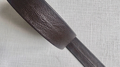
Freeze the reference that production will use
Where the design includes several nominally similar inserts, identify which geometry the reference represents. A shallower part may not resolve the appearance of a tighter corner elsewhere. The customer can decide whether representative testing is justified, but the reasoning and excluded variants should remain in the record. Do not use a shared material code as the only basis for extending a formed-part approval across different tools.
Release the material construction, direction, tool, process specification and accepted formed reference together. Define the local inspection zones and allowable appearance through the customer agreement. Avoid instructions such as “no excessive distortion” without a shared reference or measurable criterion.
Link the first production inspection to that reference. Keep incoming-roll and formed-part checks separate so a discrepancy can be located in the supply chain. Retain enough traceability to identify which material and process revision produced an affected component.
Review changes to face finish, backing, converted layers, tooling or the forming route. A new supplier sample that matches the flat master may still need the relevant formed-part evaluation. The approved combination, not the general PU label, is the repeat-order reference.
For sampling, send Wandaoleather the door-insert geometry and forming brief, including the material stack, critical appearance zones and required evidence. This gives the material comparison a defined production context.
Frequently Asked Questions
Does a flat swatch approve grain on a formed door insert?
No. Keep the flat material reference and the accepted formed-part reference separate. Evaluate the intended geometry and process before approving the complete component’s appearance.
Does SAE J361 set a universal grain-distortion limit?
No such limit follows from its visual colour-matching scope. Use the customer’s defined grain and surface-appearance requirements for the formed part.
Can elongation at break define the acceptable forming draw?
Not by itself. A rupture endpoint on a material specimen is different from an acceptable appearance endpoint on a shaped component. Validate the actual material-and-process combination.
Does local whitening always mean a colour-batch problem?
No. Compare the incoming material and converted part and investigate the mapped region. The appearance alone does not establish whether the cause is material identity, processing or another factor.
Can a free-heat shrinkage report replace a forming trial?
No. An unrestrained specimen does not reproduce the constrained, shaped production component. Keep the two assessments distinct and use each for its defined question.
What should be frozen for repeat production?
Identify the material, direction, converted stack, tool, process revision, inspection zones and accepted formed reference. Review relevant changes before transferring the approval.